Description
Detail
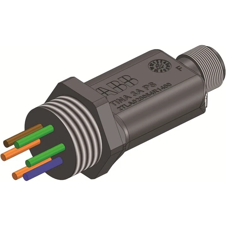
Adaptation Of Devices With 2 Positively Driven Force-Guided Contacts Like E-Stop Buttons And Key Switches, To The DYNlink Solution, With Extra Conductor For The Supply Of The Safety Device. Tina 3A Is Mounted Directly On The Device Enclosure To A M20 Cable Entry And Has A M12-5 Male Connector For Connection To The DYNlink Loop. Connection To +24VDC And 0V On The Device Side.
Specification
Bus system KNX : No
Bus system KNX radio : No
With LED indication : No
With switch function : No
Local operation/hand operation : No
Different phases connectable : No
LED controlling : No
Suitable for C-load : No
Bus system LON : No
External signal voltage necessary : No
Ethernet : No
Remote operation possible : No
Bus connection included : No
Bus system Powernet : No
Bus system radio frequent : No
Number of inputs : –
Rated operating voltage : – – – V
Input voltage : – – – V
Number of input channels : –
Max. switching current : – A
Width in number of modular spacings : –
Switching current (resistive) : – A
Output power : – VA
Max. number of switching contacts : –
Number of output channels : –
Max. switching power : – VA
Rated current : – A
Number of switch inputs : –
Max. number of venetian-blind outputs : –
