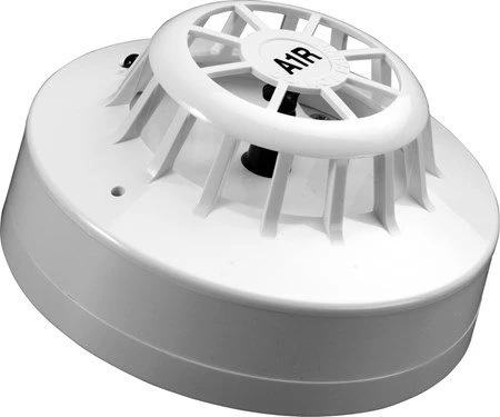
Series 65 A1R Heat Detector With Flashing Led
£20.82 inc VAT £17.35 ex VAT
Description
The Series 65 Heat Detector monitors temperature by using a dual thermistor network which provides a voltage output proportional to the external air temperature. There are 12 heat detectors in the Series 65 range designed to suit a wide variety of operating conditions. Series 65 incorporates well-proven sensing technologies, including an Integrated Circuit based on that used in XP95 analogue addressable detectors. The Series 65 range has a wide operating voltage of 933V and consists of ionisation, integrating ionisation and optical smoke detectors, four grades of heat detector and a range of bases. The detector has a moulded self-extinguishing white polycarbonate case. Nickel plated stainless steel wiper contacts connect the detector to the base. Inside the case a printed circuit board holds the signal processing electronics. A pair of matched negative temperature co-efficient thermistors are mounted on the PCB in such a way that one thermistor is exposed to give good thermal contact with the surrounding air while the other thermistor is thermally insulated. Under stable conditions both thermistors are in thermal equilibrium and have the same value of resistance. If air temperature increases rapidly the resistance of the exposed thermistor becomes less than that of the insulated thermistor. The ratio of the resistance of the thermistors is monitored electronically and an alarm is initiated if the ratio exceeds a factory preset level. This feature determines the rate of rise response of the detector. If air temperature increases slowly, no significant resistance difference develops between the thermistors, but at high temperatures a fixed value resistance connected in series with the insulated thermistor becomes significant. When the sum of the resistance of the insulated thermistor and the fixed resistor compared to the resistance of the exposed thermistor reaches a preset value, an alarm is initiated. The value of the fixed resistor is selected to set the detector into alarm state at a specified fixed temperature. The detector signals an alarm state by switching an alarm latch on, increasing the current drawn from the supply from about 50A to a maximum of about 75mA. This fall in the impedance of the detector is recognised by the control panel as an alarm signal. The alarm current also illuminates the detector integral LED. A remote indicator connected between the L1 IN terminal and the R terminal will have a voltage equal to the supply voltage less 1 volt across it and so will illuminate. To ensure correct operation of the detector the control panel must be arranged to supply a maximum of 33 volts DC and a minimum of 9 volts DC in normal operation. The supply may fall to 6 volts DC in alarm conditions if a supply current of at least 10mA is available at this voltage. To ensure effective illumination of the integral LED and any remote indicator, the supply to the detector should exceed 12 volts. To restore the detector to quiescent condition, it is necessary to restore a normal temperature level and interrupt the electrical supply to the detector for a minimum of one second.
- · Can be used on security systems
- · Electrically and mechanically compatible with Series 60
- · Proven detection performance
- · Can be used for applications where smoke detectors are unsuitable
- · Ideal for environments that are dirty or smoky under natural conditions
- · Flashing LED and magnet operated test switch option
- · Wide-operating voltage of 933 V DC
- · Wide-operating and storage temperature of -20C to +60C
- · Applications B&Bs/guest houses Cafes Restaurants Retail Small to medium buildings Dusty environments
- · IP Rating Value IP23D
Related products
-

Camera Wifi Portable 2 Way Audio Night Vision + PSU & Cable
£61.84 inc VAT £51.53 ex VAT Add to cart -

Doorbell Video IP53 + Chime
£142.73 inc VAT £118.94 ex VAT Add to cart -

Detector Motion PIR Pack=3
£122.98 inc VAT £102.48 ex VAT Add to cart -

Smart Alarm Full Control Kit
£491.92 inc VAT £409.93 ex VAT Add to cart